Dipl. Ing. A. Kutschelis & Sohn
Technische Lehrmittel Construktion
D- 59425 Unna
Germany
web: http://www.telc.de
mail: mail@telc.de
phone.: +49 (0) 2303 239999
facs: +49 (0) 2303 239990
| printable version | Level- and flow control LFIC 2000 | |||
|
"The Unit" to learn about two typical controlled members level & flow and to study the PID algorithms using original industrial components.
| |||
Control modes:
| ||||
Controlled members:
| ||||
Controller: Industrial controller or PLC | ||||
| ||||
| ||||
| ||||
Keywords: Process Trainer, Automatic Control,
Controller Tuning, Plant Technology, Process Control, Level, Flow, Control,
Automatic Control, Continuous Action Control,Compound Action Controller,
Discontinuous Action Controller, Integral Controler,Differential Controller,
Proportional Controller, PID Controller, Vaiable Feedback Controller |
||||
| ©TeLC Unna 2004 | ||||
| printable version | Interactive miniplant | |||||||||
| This mini plant combines the control of water flow, water level, water temperature and air pressure. The unit principle is similar to a steam generation and heat consumption process. Because of safety the heat generation indeed is a hot water generation. All elements are connected by PROFIBUS to an automation system. | |||||||||
Sensors:
| ||||||||||
Controlled members:
| ||||||||||
Power control:
| ||||||||||
Control: Discrete electronic controller and automation system |
||||||||||
Technical details:
|
||||||||||
|
||||||||||
Keywords: Process Trainer, Automatic Control,
Controller Tuning, Plant Technology, Process Control, Level, Flow, Temperature,
Ratio, Split Range, Feed foreward, Cascade control, Rationcascade Control,
Control, Automatic Control, Continuous Action Control, Compound Action
Controller, Discontinuous Action Controller, Integral Controler, Differential
Controller, Proportional Controller, PID Controller, Vaiable Feedback
Controller |
||||||||||
| ©TeLC Unna 2004 | ||||||||||
| druckbare Version | Miniplant FIRCA | |
| Philosophy of TeLC Miniplants: TeLC Miniplants follow a standardized design principle which adopts to some extent the real situation in an industrial plant.So is found the field department and the control department. Field and control are both equipped with original industrial instruments. The control department contains the mimetic display and the control instruments. Deviating from reality the field which is concentrated in the mimetic display is to be physically connected with the control instruments | |
| may be with pneumatic hoses or electric wiring. So the trainee has got an additional task to solve. This connecting is eased in that way that especially for the wiring needs be taken no care with normal bipolar wiring and polarity. Connecting of pneumatics and electrics feels equal. The standardisation of the TeLC Miniplants goes so far as the dimensions height 1.95m and depth 0.65m are equal. Only width differs between 2.2 and 2.9 m and of course weight. Within the abbreviation naming of the units is indicated the control task and instrumentation so e.g. here FIRCA means: Flow - Indication - Registration - Control - Alarm | ||
Wide range of Training Tasks:
| ||
Built-up of FIRCA:
| ||
| ©TeLC Unna 2004 | ||
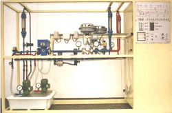
| printable version | Miniplant LIRCA | |
| Philosophy of TeLC Miniplants: TeLC Miniplants follow a standardized design principle which adopts to some extent the real situation in an industrial plant.So is found the field department and the control department. Field and control are both equipped with original industrial instruments. The control department contains the mimetic display and the control instruments. Deviating from reality the field which is concentrated in the mimetic display is to be physically connected with the control instruments | |
| may be with pneumatic hoses or electric wiring. So the trainee has got an additional task to solve. This connecting is eased in that way that especially for the wiring needs be taken no care with normal bipolar wiring and polarity. Connecting of pneumatics and electrics feels equal. The standardisation of the TeLC Miniplants goes so far as the dimensions hight 1.95m and depth 0.65m are equal. Only width differs between 2.2 and 2.9 m and of course weight. Within the abbreviation naming of the units is indicated the control task and instrumentation so e.g. here LIRCA means: Level - Indication - Registration - Control - Alarm | ||
Wide range of Training Tasks:
|
||
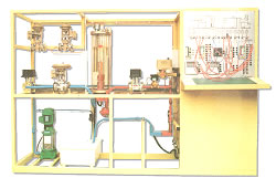
Built-up of LIRCA: The fluid flow is easy to ceive: By this configuration are created 3 dependant control loops: FIC, LIC and PIC. The pneumatic 3-pen recorder is for high speed registration. The alarm device is activated by the alarm actuator in the field. The delay units can be intermitted into every signal path. The pump delivery is variable through a bypass. Flow can also be restricted by a handvalve before the entry to the vessel. The control loops FIC and LIC can be connected in cascade with FIC as follower to improve control performance at upstream disturbances. Width 2.9 m net weight 220 kg. services AC 3-phase and pressed air. |
||
| ©TeLC Unna 2004 | ||
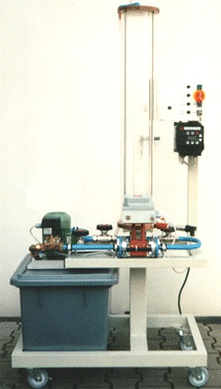
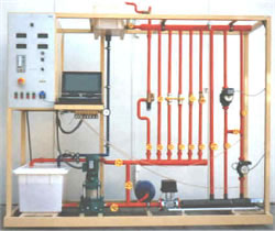
| printable version | Pumps and Valves | |
| The unit is for the training of waterhydraulics which are used in house installations for heating and water supply. Installations:
| |
Valves characteristics test:
| ||
Measuring:
| ||
Automatic Control:
| ||
Terminal for PC
connection:
| ||
Details:
| ||
| ©TeLC Unna 2004 | ||
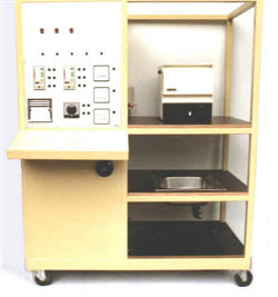
| printable version | Miniplant TIRCA | |
| Philosophy of TeLC Miniplants:
TeLC Miniplants follow a standardized design principle which adopts to some extent the real situation in an industrial plant.So is found the field department and the control department. Field and control are both equipped with original industrial instruments. The control department contains the mimetic display and the control instruments. Deviating from reality the field which is concentrated in the mimetic display is to be physically connected with the control instruments may be with pneumatic hoses or electric wiring. So the trainee has got an additional task to solve. This connecting is eased in that way that especially for the wiring needs be taken no care with normal bipolar wiring and polarity. Connecting of pneumatics and electrics feels | |
| equal. The standardisation of the TeLC Miniplants goes so far as the dimensions hight 1.95m and depth 0.65m are equal. Only width differs between 1.8 and 2.9 m and of course weight. Within the abbreviation naming of the units is indicated the control task and instrumentation so e.g. here TIRCA means: Temp - Indication - Registration - Control - Alarm | ||
Wide range of Training Tasks:
| ||
Buildup of TIRCA: TIRCA is a heat treating process. The furnace heats up to 1000 °C rather fast. The special isolation material efects a not too longtime accumulation of heat. The water basin down under the furnace is for cooling the piece of metal. The metalpiece and a pair of pliers belong to the equipment. | ||
Electric power installations:
| ||
Controllers:
| ||
Registration and indication:
| ||
Details:
| ||
| ©TeLC Unna 2004 | ||
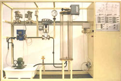
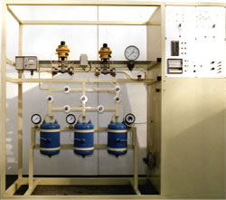
| printable version | Miniplant PIRCA | |
| Philosophy of TeLC Miniplants:
TeLC Miniplants follow a standardized design principle which adopts to some extent the real situation in an industrial plant.So is found the field department and the control department. Field and control are both equipped with original industrial instruments. The control department contains the mimetic display and the control instruments. Deviating from reality the field which is concentrated in the mimetic display is to be physically connected with the control instruments may be with pneumatic hoses or electric wiring. So the trainee has got an additional task to solve. This connecting is eased in that way that | |
| especially for the wiring needs be taken no care with normal bipolar wiring and polarity. Connecting of pneumatics and electrics feels equal. The standardisation of the TeLC Miniplants goes so far as the dimensions hight 1.95m and depth 0.65m are equal. Only width differs between 2.2 and 2.9 m and of course weight. Within the abbreviation naming of the units is indicated the control task and instrumentation so e.g. here PIRCA means: Press - Indication - Registration - Control - Alarm | ||
Wide range of Training Tasks:
|
||
Buildup of PIRCA: A digital electronic controller is to be connected to the pressure control loop. 2 lines can be activated for the control. The pneumatic control valves have different capacity. For interfacing are used the p/I-transmitter and I/p-converter. A system of needle valves with positionscales together with the 3 reservoirs allow the simulation of delays up to third capacity. For data logging an electric 3-pen recorder with variable paper speed is existing. The alarm device can be connected to the alarm actuator in the field. |
||
Dimensions:
|
||
| ©TeLC Unna 2004 | ||
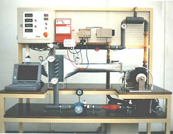
| printable version | Building Automation | |
| Heatexchange water-air, Centrifugal Fan, centrifugal pump , Automatic Control, Building Automation, Accounting, PC-Data-acquisition The unit is an Air Heater with Hot Water circuit . The temperature of which is controlled by on/off controller, continous quality c. and mixing c. | |
It carries different technical elements
that grant multipurpose use:
|
||
| rollable unit w. dimensions: 1.5x0.65x1.8m
weight: 180 kg. services 230V AC visit also Fan & Thermic teststand which is an extraction of this unit. |
||
| ©TeLC Unna 2004 | ||