| printable version | Transparent engine | |||||||||||||||||||
|
| |||||||||||||||||||
The well known Transparent
engine coupled with our power absorber and equipped with our systems explains
the internal combustion process of a 4-stroke Otto engine better than anything.
Newly equipped it matches the requests on explaining the future automotive
methodes fundamentally:
| ||||||||||||||||||||
All these features
should result to:
| ||||||||||||||||||||
| The measuring system enables the evaluation. | ||||||||||||||||||||
| Fully variable valves actuation –
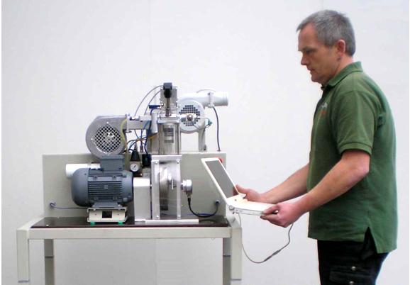
timing and lift – for a laboratory The 4-stroke engine which is well known for many years in laboratory practice was equipped with a piezo-pneumatic valve actuator. The performance is controlled with the mouse pointer of the PC during running. The engine is incorporated in a test rig whose control, data acquisition and data display is exclusively executed on the PC. The real-time data acquisition includes the permanent indicating with displaying in p/V or p/? - diagram and with the calculation of the averaged indicated pressure. | |||||||||||||||||||
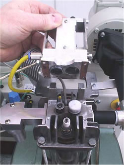
| 1. The engine The engine base is a mono-cylinder with 70 ccm stroke volume and a compression ratio of 1:4. The cylinder wall is glass. The piston runs dryly. The connection-rod bearings are dryly running needle rollers. The transparent design of the engine allows observation of crankshaft, piston, valves, ignition and combustion. Figure 1 The usable speed range is between 350 and 2500 rpm. The hanging valves are directly operated by cup-like pneumatic pistons (Figure 1). The auxiliary pressed air flow is conducted by a way-valve that is driven by a piezo-actuator. The high flow-rate of this fast way-valve makes this functionality possible. The mixture is made by an injection pump in the intake. The pump performs a mono-stroke of adjustable height, driven by a piezo-actuator. Partial load is preferably executed by “Early intake valve closure” or “Late intake valve closure”, but it is also possible to activate one throttle situation in | |||||||||||||||||||
| the intake for comparison.
Reducing the pressure of the auxiliary air from 2,8 down to 2.0 bar effects
a reduction of the valve lift and thus a reduction of the time opening square.
The electronic ignition is also fully variable in terms of timing and dwell. The upper panel of the software screen contains the control elements (Figure 2) : A status- and a speed shifter control the engine performance. The engine needs a high resolution field of characteristic data sets for all operation conditions. These have to be elaborated by the student and are saved as data files. With loading of such a data file the engine is immediately driven into the operation point, including the set speed. The control elements for saving and loading can be found in the control panel of the screen. (Figure 2). | ||||||||||||||||||||
| ||||||||||||||||||||
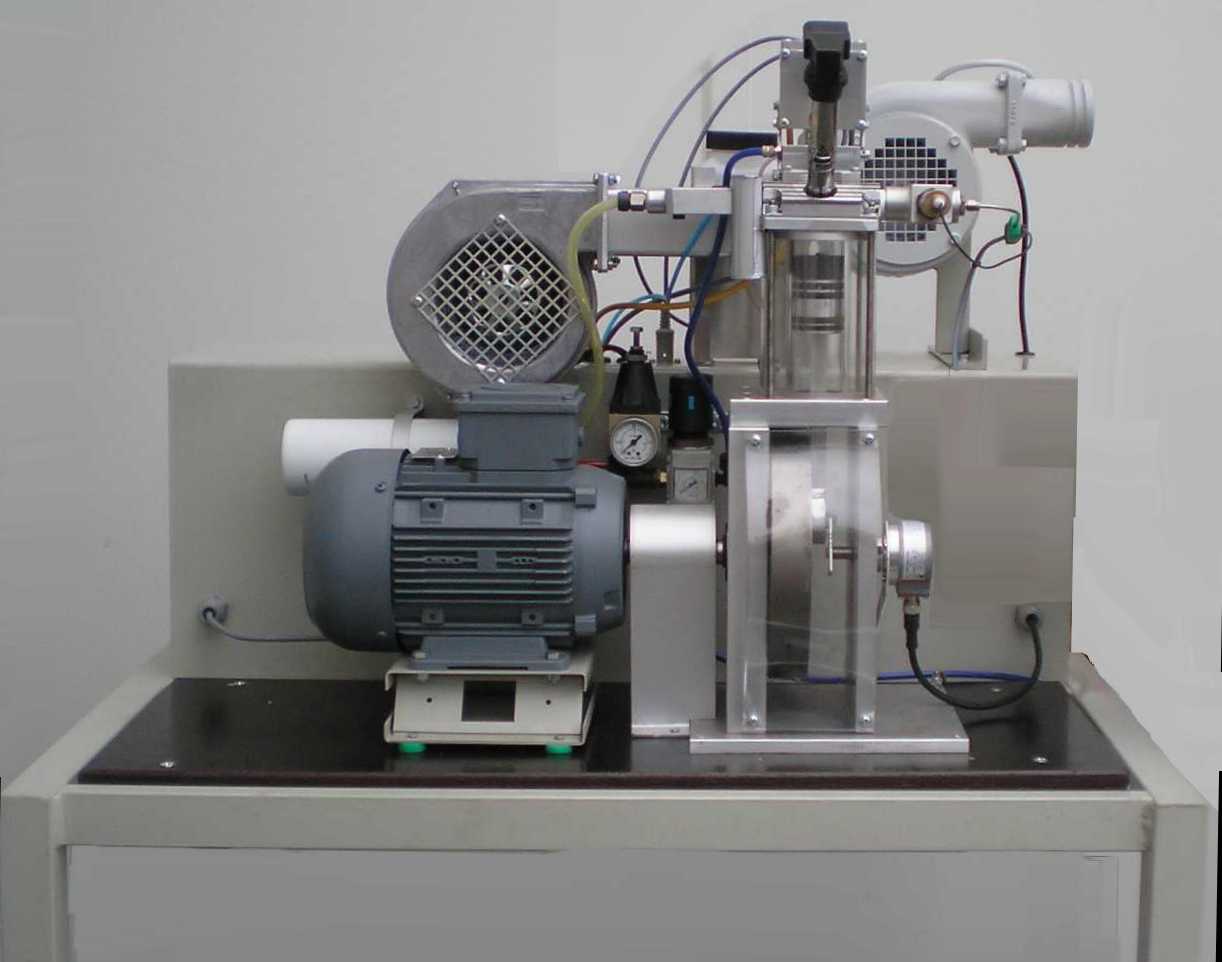
| 2. The test rig Important part of the test rig is the directly coupled electric motor/generator. A special elastic shaft joint governs the extremely disharmonic force transmission of the mono-cylinder. The electric motor/generator is in swivel bearings and has got a torque adaptor which is combined with a force sensor. The electric engine governs the combustion engine and functions as power absorber and engine starter. The engine needs an additional piston cooling by an air ray similar to the piston cooling with oil spray. This is automatically controlled by the test stand depending on exhaust temperature and power. The exhaust gas is cleaned by a special catalytic converter. A fan leads the exhaust gas through a pipe and a flex hose to the outside. | ||||||||||||||||||||
3. Measured quantities
The data acquisition captures 40 samples of each non-indicated measured quantity per revolution. The quantities value is equal to the arithmetic average. The resolution for the indicator diagram is 200 values per power cycle. The control timing actions are refreshed 400 times per power cycle. | ||||||||||||||||||||
| 4. The measuring display All measured quantities as well as the derivative quantities power, specific fuel consumption and average internal pressure are displayed by bargraphs. A fast refreshing table displays all quantities as exact digitals. All values can be selected for plotting. An extraordinary feature is the test stand's indicator mode which works simultanously to all other functions. The data is displayed on a software-oscilloscope. Figure 3 shows a minimized p/alpha-diagram and an enlarged one in figure 5. The indicator diagram can be configured as p/? or p/V diagram with optional focus on the gas exchange phase ((Figure 7). Not only the internal cylinder pressure is indexable, but also torque, intake air flow and voltage of the oxygene probe. ((Figure 4 u. (Figure 6) Indicator diagrams can be saved with the indicator diagram browser, presenting the recently captured diagrams for further evaluation. Stored data files includes the values of all quantities, especially the control timings. A powerfull export function provides easy export to external software. The software package includes powerfull functions for the post editing of recorded data and preconfigured evaluation templates (Figure 8). Finally | ||||||||||||||||||||
|
| |||||||||||||||||||
|
| |||||||||||||||||||
|
| |||||||||||||||||||
Keywords: engine dynamometer, engine test
cell, engine tester, engine test stand, testcell, motor tester, engine
test software, power tester, transparent engine, 4-cycle engine, oil-free
engine, engine test stand,power absorber, internal combustion test bed,
4-cycle engine trainer, automotive education, Valvetronic, Transparent
Engine Technique Stand,fully variable valve actuator, monocylinder 4-stroke
Otto, transparent cylinder, crankshaft, piston, valves, ignition, combustion,
different fuels, intake injection,Injection volume, timing are fully variable
adjustable, intake, outlet, open,close, valve lift, time opening square,
electronic ignition, free variable, dwell, cathalyst, intake airvolume,
exhaust tubing, oxygene probe exhaust gas temperature, rendered torque,
force sensor, sviwel support, rollable stand, ignite, inject,air fuel
mixture, rich, poor, fuel injection, ignition and valves timing, ignition,
early, late, inlet outlet valve overcross, Indicating mode, internal cylinder
pressure, intake valve, outlet valve, compress, cold start, warm up, injection
quantity, Compression curve, long ignition delay, Late intake closure,inflammation,
Early intake closure, fluid condensation, specific fuel consumption, stoichiometric
mixture, variable valve actuator, throttle, Partial load, early inlet
valve, late inlet valve close, gas exchange phase, indicating aspirated
air flow, indicating torque, 4 stroke engine, effect of ignition, valve
lift, vva, VVA |
||||||||||||||||||||
| ©TeLC Unna 2004 | ||||||||||||||||||||